Canyon Mountain
Serving Canyonville, Riddle, Tri-City and Myrtle Creek at 91.9 MHz
Location: two miles south of Canyonville (geographic coordinates and map).
Pictures were taken in February 2008.
Canyon Mountain
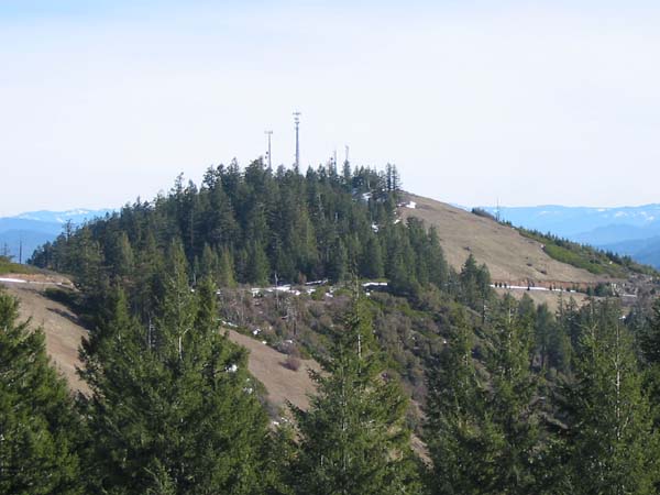
Cell phone towers adorn the summit. This view looks east from the access road.
The Radio Site
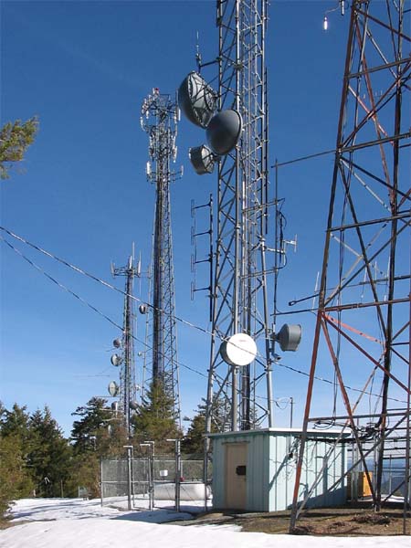
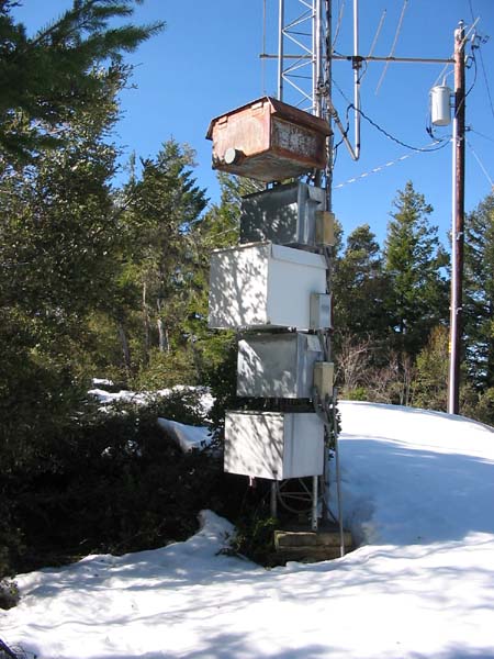
This area has become crowded. Recent additions include two cell phone towers and a communications tower, each with a substantial equipment shelter and a heavy-duty security fence.
The tower with the faded red paint (on the right side of the picture, above) is a historic airway beacon. The U.S. mail service began installing these towers in the 1920s in order to guide the airmail pilots. Now (in 2008), it is likely that this tower is more than 75 years old. The metal building at the base of the tower houses numerous radio transmitters. The tower is heavily loaded with antennas, as seen below.
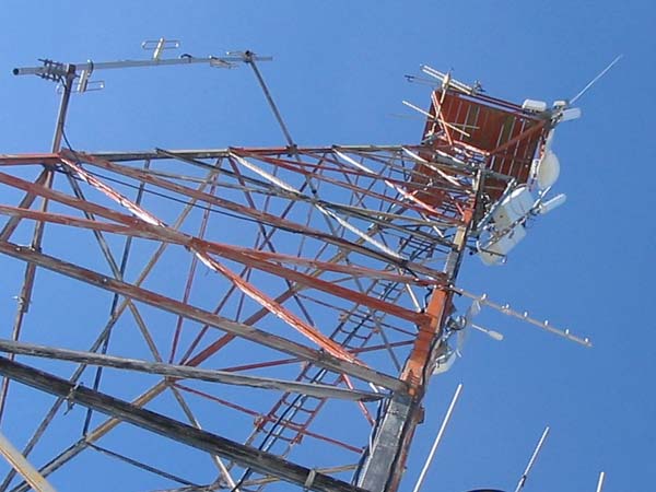
The Historic Airway Beacon Tower
When we were installing the translator, one of the volunteers liked to climb the tower and eat lunch from its upper deck while enjoying the lofty view. There were no antennas on the tower at the time.
The Oldest Tower
The four large towers nearly obscure the small tower on the right. It was already in place when the KSOR translator was installed. It was the operating base for the KEZI and KOBI TV translators.
The First Translator
This installation is typical of the early days of TV translators. If a building was not available, a metal box on the tower protected the translator from weather and vandalism, and the transmitting antenna was mounted above. If receiving on an adjacent channel, the antenna would sometimes be placed several hundred yards away or hidden behind a feature of terrain in order to shield it from the transmitting antenna.
The first KSOR translator at Canyon Mountain was installed in a similar fashion. A two-inch galvanized pipe supported the transmitting antenna, and a fabricated steel box housed the Tepco J-317 translator. The receiving antenna was placed about one-hundred yards to the west. RG-6 coaxial cable for the receiving antenna was left lying on the ground.
The Tepco J-317 was unreliable. In order to keep the translator on the air, it was necessary to make adjustments two or three times a week. It was during these frequent visits that we discovered the squirrels' appetite for the silicone gel inside the RG-6 cable. They were biting off big chunks, through the outer sheath, right down to the center conductor. Because of this, we adopted the practice of placing coaxial cable inside steel conduit.
The Second Translator
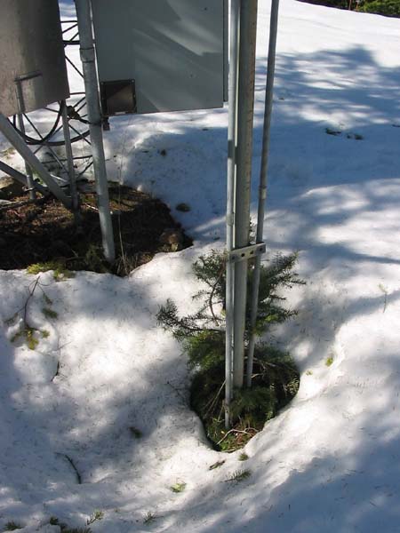
When the XL-FM translators became available, we were eager to replace the troublesome J-317. By then, we had devised a new strategy. Because the budget was not adequate to build a concrete-block building, we installed the translator underground in a ferrocement vault. After many months of routine translator failures, the new translator and vault provided welcome relief from the incessant need for maintenance.
The vault is still there, below the snow, beneath the surface of the ground. Steel conduits surround the coaxial cables for the receiving and transmitting antennas, which are directly above. Below ground, a 90-degree elbow brings each conduit through a watertight seal in the vault wall. For AC electric power, another conduit runs underground to the meter base on the original tower, mentioned above.
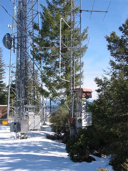
The Antennas
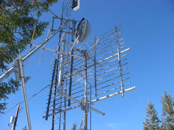
Recent additions surround and dwarf the structure put in place for KSOR's second translator. A triangular tower has been erected close by on the west side, and its diagonal support passes over the top of the original receiving antenna.
The large screen assembled from one-half inch pipes is unique to the translator system. The pipes are spaced 0.1 wavelength at the operating frequency of the translator. This screen acts like a black shade, isolating the receiving antenna from the transmitting antenna. The receiving antenna is on your (the viewer's) side, and the transmitting antenna is on the far side of the screen – not easy to see. In fact, there are so many pipes and wires in this photo that it is difficult to comprehend the structural configuration.
Historic Remnants of a TV Receiving Antenna
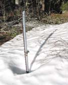 On the north side of the access road, several hundred yards west of the radio site, there are artifacts from an early translator that have been overlooked in the sweep of recent construction. To the left, an ordinary steel fence post was driven into the ground in order to support a short length of thin-walled steel conduit. This is the remains of a rudimentary mast for a TV receiving antenna. Bailing wire bound the conduit to the fence post, and bailing wire was probably used as guy lines to steady the antenna. By today's standards, it was quite simple and rustic, but it proved adequate for the translator operation.
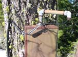 A few feet away, a steel box is nailed to a tree. In the picture at the right, a coaxial cable enters the box in a simple way that prevents the entry of rainwater. This box would have held the line amplifier for the coaxial cable. After increasing its strength, the signal picked up by the receiving antenna was sent on to the TV translator at the summit.
Dennis Hunt, the Chief Engineer for KEZI-TV 9 and KEZI-DT 44 in Eugene, has firsthand knowledge of these historic artifacts. He has been an engineer with KEZI-TV since 1973.
As near as I can tell, the KEZI translator went on the air in the summer of 1962. It was originally an EMCEE HRV 1-watt translator, and there was a building to house the equipment. At that time, a quad receive antenna was located about 1000 feet west of the site. That is the remnant you see to the north of the road. I believe that it was placed there because the signal from KEZI was weak at the top of the hill. The other translator on the site was for KPIC at the time.
In 1967, it looks like a translator for KOBI was placed on the site. . .
In 1975, a TV Technology (Keith Anderson) T-99 replaced the Emcee. Sometime around then, the building was abandoned and the box placed on the tower. In 1996, the old rx antenna was abandoned for a UHF Ch 53 feed from our Roseburg translator at the top of the hill. (Dennis Hunt, email, February 25, 2008)
Documents from the FCC Database
(http://www.fcc.gov/fcc-bin/fmq?list=0&facid=62955)
FCC Authorization 2008
Initial License Grant 1980
Topographic Map
Canyonville Quadrangle, U. S. Geological Survey
CONTOUR INTERVAL 40 FEET
Geographic Coordinates: 42° 54' 06"N, 123° 17' 07"W (NAD27)
Antenna Height Above Mean Sea Level: 1,037 meters (3,403 feet)