Engineering
The Design, Installation and Maintenance of the Translator Network
Contents
Translators
![]()
 Defined
![]() Keith Anderson T-99FM
Keith Anderson T-99FM
![]() Tepco J-317
Tepco J-317
![]() Television Technology XL-FM
Television Technology XL-FM
Antennas
![]() Scala
Scala
![]() Quad Array
Quad Array
Modular Tower System
![]() Deadman
Deadman
Ferrocement Vaults
Engineering Criteria and Practices
![]() Signal to Noise Ratio (SNR)
Signal to Noise Ratio (SNR)
![]() Receiving Antenna/Fade Margin/Signal Strength
Receiving Antenna/Fade Margin/Signal Strength
![]() Calculations/Knife-Edge Diffraction
Calculations/Knife-Edge Diffraction
![]() Friis Equation
Friis Equation
![]() Receiver Overload
Receiver Overload
![]() Antenna Location
Antenna Location
FCC Database
Transportation
Translator Stations
An FM translator station rebroadcasts the signal of a primary FM station or the signal from another translator. A translator does not originate its own programming.
A booster station is essentially a translator station that receives and transmits on the same frequency. Boosters were not used in the translator network.
The Keith Anderson T-99FM Translator
KSOR's first translator was a T-99FM. It was nearly identical to the T-99 used for television.
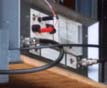 The design reflected early solid-state technology, appearing more like an experimental prototype than a production model. It had no printed-circuit boards, but used point-to-point wiring with components being soldered in place by hand, one at a time. It did not have a custom-manufactured cabinet, but used an off-the-shelf metal cabinet manufactured by Bud Industries. (The Shadow Cabinet remains a standard catalog item.) These pictures record the T-99 television translators being used at Port Orford in 1982.
The T-99 was designed when TV translators were still a new idea, and the radiofrequency spectrum was not crowded. The 6 MHz bandpass was appropriate for TV, but adjacent-channel rejection was poor. Frequently, when translating to an adjacent channel, the receiving antenna had to be placed at a considerable distance or hidden behind a small hill in order to keep the T-99's transmitter from interfering with the incoming signal. For KSOR's first translator at Fielder Mountain, the receiving antenna was located in the shadow of the ridgeline to isolate it from the transmitting antenna.
In order to provide service for FM broadcast, the translator used component values that functioned on the appropriate FM operating frequency, but the 6 MHz bandwidth remained unchanged. FM frequencies are allocated on 0.2 MHz increments, so numerous stations could be simultaneously received and rebroadcast. When first operating at Fielder Mountain, if there had been more than just the KTMT-FM signal within that 6 MHz bandpass (as there is today), all of them would have been rebroadcast!
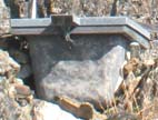
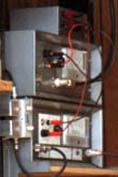 This image illustrates other features of the T-99. The lower box is the translator, but the upper box is an amplifier. The T-99 translator had an output power of one watt. If you wanted ten watts, you just added the ten-watt amplifier that looked like its twin.
There was no internal power supply to provide operation on 120 VAC. A small power supply sat nearby, and external wires made the connection to banana jacks on the front panel. The silver boxes on the left side of the T-99 are filters, similar to what we used on Fielder Mountain. This translator required a variety of external components to enable its operation.
Keith Anderson designed and manufactured the T-99, later selling the manufacturing rights to Television Technology Corporation (TTC). KSOR purchased its T-99FM from TTC. At the time, we had no understanding of the inadequacy of the T-99FM, and no idea of the problems developing in the translator marketplace. Much later, we would learn of the effort being made by TTC to design a superior translator and bring it to market.
The Tepco J-317 Translator
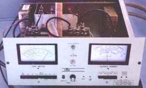
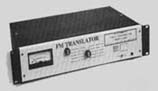 The J-317 was a good translator in many respects. Its receiver was substantially more selective and more sensitive than the T-99FM's. In all but the most demanding electronic environments, it would perform well. The circuit design was sophisticated, and its construction incorporated printed-circuit boards and modern manufacturing methods. It included a built-in power supply for 120 VAC and offered a 28-volt option for solar applications. On an electronic test bench, it delivered a stable output having 10 watts of power.
Following KSOR's first translator for Grants Pass, a project was initiated for five additional mountaintop sites: Canyon Mountain, Mt. Nebo, Scott Mountain, Eight Dollar Mountain and Paradise Craggy. The station purchased five Tepco J-317s, including one solar-powered model for Paradise Craggy.
Unfortunately, this translator had a serious flaw. When exposed to the changing temperatures of a mountaintop environment, the transmitter section would become wildly unstable. The power amplifier would self-oscillate, generating its own radio signal with no control of the frequency. On many occasions, this translator obliterated the input signals of other translators and even a cable television system.
Having accepted listener donations for the construction of five translator sites, there was enormous pressure to have them function reliably. For a time, a large part of the engineering effort was directed to keeping the J-317 translators on the air. Listeners in communities served by these translators were disappointed with the inconsistent service. To the KSOR engineering department, it was a nightmare.
Television Technology's XL-FM Translator
 A convention of the National Translator Association drew our attention to a new offering by Television Technology Corporation. Jon Sawyer, their design engineer, presented preliminary ideas and tentative specifications for a new FM translator. The concept sounded great, but we were dubious about ever seeing such a unit available for purchase. Up to that point, our experience with translators had been less than encouraging.
After the convention, we talked with Jon on the telephone once or twice a week for many months. He demonstrated a comprehensive understanding of translator operation and was generous in sharing his knowledge. We can thank Jon for invaluable help with the design of the network.
We pleaded for a translator, but TTC was insistent about completing its prototype testing. Eventually, we received a translator and were greatly relieved. At Mt. Nebo, the J-317 had never functioned correctly. Although this was the first XL-FM off the assembly line, it operated flawlessly and dependably from the moment we turned it on.
It took time to replace the other J-317s. We were in competition with a large number of customers who were clamoring for the new XL-FM.
Scala Antennas
There was no serious competition: Scala made the best antennas for translators. More than two decades of service in the translator network have demonstrated their reliability. They are manufactured in Medford, Oregon and sold worldwide.
Three models were used in the translator network:
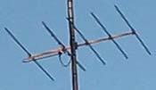
HDCA-5 |
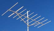
HDCA-10 |
CL-FM |
The wind survival rating for all of these antennas is 120 mph. The CL-FM log-periodic antenna has the greatest mechanical and electrical tolerance for ice buildup. It was chosen for all elevations above 6,000 feet. Where the wind has blown chunks of ice from nearby towers, we find that the antennas have sustained serious damage. (See Damaged Antennas and Towers.) On the other hand, the CL-FMs at Chestnut Mountain appear brand new after being in service for 26 years.
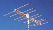
The Quad Array
 The array of four antennas made the signal being received four times as strong. Its gain was 6 dB greater than one of the antennas operating alone.
This array was designed for cable TV systems. Before the distribution of TV and FM radio programs by satellite, cable systems would pick up signals directly from terrestrial transmitters. Because of the uncertainty about the strengths of the translator signals arriving at Port Orford and Crescent City, one of these antennas was used at each site. It proved to be a poor choice. Storm winds destroyed the antenna at Port Orford, and salt-air corrosion destroyed the antenna at Crescent City. Each was replaced with a single Scala HDCA-10.
The Modular Tower System
A wide selection of antenna towers was available commercially, but none offered the particular combination of strength, economy and flexibility needed for translator installations. The towers didn't need to be high, but they did need strength sufficient to withstand strong winds and heavy ice loads. The components needed to be modular so they could adapt to a variety of antenna combinations and also carry solar panels at several sites.
The modular tower system used commonplace steel pipes as structural elements that were assembled in creative ways using custom-designed fasteners. The idea came from the simple Tinkertoy Construction Set of the 1940s, but was adapted for steel pieces on a much larger scale.
Custom-Designed Tower Fasteners
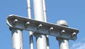
Cross Piece |
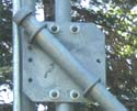
Square Plate |
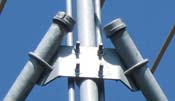
Angle Bracket |
The cross piece provided 12-inch spacing for double tower sections, and a strong attachment for a single pipe that would extend the tower height.
The square plate secured a vertical tower section to a diagonal brace at a 45-degree angle. Where needed, it could also join pipes at a 90-degree angle.
The 45-degree angle bracket supported a single vertical pipe with two diagonal braces.
Custom components were hot-dip galvanized in order to provide the greatest corrosion protection. One-half-inch by three-inch galvanized-steel U-bolts, which were standard chain-link fence hardware, provided attachment to the two-inch, Schedule 40 steel pipes. Galvanized caps were placed on both ends of pipe sections, and any bare, exposed steel was coated with cold-galvanizing spray paint.
A variety of configurations:
Single tower � 18 feet above the ground (Park Mountain)
Single tower � 26 feet above the ground (Central Hall � 29 feet above the roof)
Single tower � 37 feet above the ground (Chestnut Mountain and Agency Hill)
Double tower (Stukel Mountain)
Triple tower (Park Mountain)
Sextuple tower (Iron Mountain � an inclusive picture is not available)
On the pole mount (Port Orford)
Side pole mount (Wedderburn Peak and Port Orford)
Between pole mount (Crescent City Corporation Yard)
Wall mount (Jefferson School)
An additional use for the custom-made cross piece:
This was what I used to make "portable steps". With three of four of these you could "U bolt" them to the 2" pipe as you climbed to get to the top to work on the antennas and remove them as you climbed back down. Often I traveled without a ladder, so finding a few of these really helped me to easily access the tops of the structures. (Todd Cory, email, February 13, 2008)
An unusual installation procedure:
Commercial radio towers typically use a concrete pad to support the base, and concrete anchors for the guy lines if the tower is not freestanding. The use of concrete would have required additional labor and cost at any site, and delivery by commercial concrete truck would have been unusually difficult at some locations. We found a way to do without.
 In construction, a deadman is an anchor that utilizes the weight of soil or rock above it for its stability, rather than its own weight, such as a concrete anchor. We had deadmen custom fabricated from quarter-inch steel plate. Holes were placed for attachment to either one or two pipes, as illustrated by the drawing on the left. They offered a strong base for either a diagonal brace or vertical tower section. Understandably, the deadmen could not be photographed in 2008 because they remain in service, buried below the surface of the ground.
Before the backhoe arrived at an installation, the tower components would be assembled and the deadmen attached. First, the backhoe would dig a hole for the vertical tower section. Two of us would set the tower in place, and the backhoe would immediately backfill over the deadman. We had a carpenter's level to keep the tower vertical, and a strong rope tied to the top so we could pull the tower section into place with brute force, if necessary. Next, one by one, the side braces would be attached to the tower section and each deadman buried in a similar manner. Installing the tower for the receiving antenna, generally located some distance from the transmitting antenna, would repeat the process.
Once the towers were in place, the backhoe would dig a trench for the steel conduit that housed the coaxial cable for the receiving antenna. As the backhoe proceeded, we followed, placing the conduit with its coaxial cable in the trench. When the trench was finished, the backhoe would return to the starting point to begin backfilling, and we would finish laying the conduit. We did not delay the backhoe operator at any point. Using the deadmen facilitated efficient use of the backhoe on only a single trip and avoided the cost of concrete.
Deadmen were used for all or part of the installations at the Stonecypher, Kenyon, Canyon, Agency, Loma Linda, Park, Grey, Oak, Eight Dollar and Harbor sites.
Now that the modular tower system has been in service for more than 20 years, certain shortcomings are evident. These are discussed under the topic of Damaged Antennas and Towers on the Observations page.
Ferrocement Vaults
 These vaults were designed as underground enclosures for translators. They were an inexpensive way to attain security and temperature stability. We became aware that one of many factors causing the failure of solid-state equipment was the daily and seasonal variation of temperature. The vaults didn't solve every problem, but they were a good compromise solution for several translator sites.
 The vaults were made using the ferrocement boat technology of that day. A plywood mold was made in to form of the inside of the vault. Steel fencing material was placed around the mold, and then a special concrete mixture was troweled in to a thickness of about one and one-half inches. The sides of the mold were tapered ten degrees so that the vault could be removed after the concrete hardened. The concrete was then cured inside a plastic tent for several days at high temperature and high humidity. Finally, the vault was coated inside and out with a black, marine-grade epoxy paint. The paint would endure well underground.
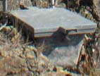
The vault pictured here is the only vault to be used above ground. The sunlight at Paradise Craggy has caused deterioration of the epoxy paint. Where exposed to sunlight, epoxy needs UV protection.
Each vault had a plywood lid that included a one-inch foam board for insulation. In these pictures, the additional cover was made from quarter-inch galvanized steel.
At the Agency, Loma Linda, Park and Eight Dollar Mountain sites, both ferrocement vaults and deadmen were used to simplify the installation.
Engineering Criteria and Practices
The audio quality of the programming being carried by the translators was maintained by the careful handling of radiofrequency signals. There were inherent limitations in the analog technology and in the specific electronic design of each type of translator. The engineer's challenge was to choose mountaintop sites and antenna combinations that would optimally preserve the listening quality while keeping an eye on cost and maintenance concerns. There were a number of technical factors in the balancing act:
Signal-to-Noise Ratio (SNR)
Advances in digital recording media and digital circuitry have brought a substantial improvement to the audio quality of FM broadcasting. With the original analog equipment at KSOR, keeping noise and distortion at a minimum was an ongoing challenge. We had to keep an eye on every link of the broadcast chain: the vinyl phonograph records and reel-to-reel tape recorders in the studio, the microwave studio-transmitter link (STL), the signal leaving the main transmitter on Mt. Baldy, and the rebroadcast of KSOR by each translator. Every part of the system was close to the edge with respect to acceptable sound quality.
The transmitter on Mt. Baldy operated with an SNR of only slightly more than 60 dB, as required by the FCC. (The STL was the limiting element in the transmitter's noise performance.) If all factors in the signal paths leading out from Mt. Baldy were ideal, each translator would degrade the SNR by 3 dB. Thus, the Kenyon, Oak and Harbor translators � each being the last in a line of four translators � operated with an SNR of little more than 48 dB. A larger SNR was desirable, but this represented the best available from analog technology and good translator design. It was a challenge to prevent further degradation of the signal quality anywhere in the network.
Improvement of the STL's noise performance would have helped every translator, but correspondence with the manufacturer provided no help.
Receiving Antenna
The strength of the signal appearing at the input of a receiving module affected the noise performance of a translator. A clear, 32-microvolt FM stereo signal produced a 50 dB signal-to-noise ratio (SNR). Taking this as the minimum acceptable SNR, each signal path in the translator network was designed to have a 20 dB fade margin (ten times the voltage or 100 times the power required for a 50 dB SNR). Thus, 320 microvolts was the desired signal strength at the receiving module. This mitigated the loss of program quality if the signal strength decreased for any reason.
In most cases, a single receiving antenna was sufficient to produce the desired 320 microvolts. For the Iron Mountain translator, two quad transmitting antenna arrays were chosen to insure sufficient signal strength over long distances. At Camp Six, the quad transmitting array was chosen because of the low power of the translator and the very small target to which the signal was being delivered.
Calculations
The strength of any signal arriving at a translator's receiving antenna was easily determined with mathematics and maps. It was necessary to travel to each site only to evaluate local terrain, soil type and to look at existing facilities, but it wasn't necessary to run a test signal.
To predict the strength of any signal arriving at a translator's receiving module, each factor affecting the loss or gain of strength, expressed in dB (decibels), was either subtracted from or added to the output power of the signal source, expressed as dBmW (decibel level referenced to one milliwatt):
the free space path loss from the Friis equation (below),
the gain of both transmitting and receiving antennas expressed in dBi (isotropic),
the loss in the transmitting and receiving coaxial cables, and
the loss from knife-edge diffraction, if any (discussed on the Port Orford page).
The result was converted to the signal strength in microvolts that would appear at the 70-ohm antenna terminal of the receiver module. (These calculations assumed a clear signal path with no surface reflections, i.e., no Fresnel zone interaction. Measurements made after installations were complete were found to be in close agreement with the mathematical predictions.)
Friis equation
This form of the Friis transmission equation easily calculated the path loss of a radio signal between two points:
where A
f
d
= free space loss attenuation, dB
= frequency, MHz
= distance, miles
Receiver Overload
The strength of any signal appearing at the antenna terminal of the receiver module needed to be less than 100,000 microvolts in order to prevent receiver overload. This value was specified in the operating manual for the XL-FM translator. Higher levels would cause distortion of the signal being rebroadcast. The translator itself or any other transmitter in the vicinity could cause overload. (50,000 microvolts was specified for those translators optimized for solar power.)
Antenna Location
The strength of the translator's own signal being radiated from its transmitting antenna determined the location of the receiving antenna.
The strategy in locating the antenna was to maximize reception of the signal that was arriving for rebroadcast, and to minimize reception of the translator's own output signal. This was frequently done by choosing a location that placed the two sources at a right angle, thus taking advantage of both the maximum and minimum points of reception on the receiving antenna. For each antenna, the manufacturer provided a polar plot of gain, so the minimum separation was easily established using the Friis equation.
The placement of a transmitting antenna was restricted by local topography because of the need to maximize radio coverage to potential listeners. Even where an existing building was used for the translator, or where an existing tower was used for the transmitting antenna, there was considerable flexibility in choosing a location for the receiving antenna.
The FCC Database
The FCC Database includes information from paper files that were generated before the FCC adopted digital technology. Within the files converted to digital format, there are numerous errors in the geographic coordinates, frequencies, dates and other information. It seems that some files may have been lost and others transcribed incorrectly.
The FCC documents recorded on this website were downloaded in 2008. They are not error-free.
Transportation
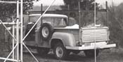 The radio station purchased this 1970 Dodge Power Wagon, a 4x4 with power-takeoff winch, as surplus property from the State of Oregon. The automotive shop at the Oregon State Penitentiary put new rings in the engine and a new coat of institutional green paint on the exterior. It had seen hard service before the station obtained it. The demands of installing translators were harsh and unusual, well beyond those of recreational driving on mountain roads.
We replaced the old truck bed because the wood was splintered and weak. We added a full length carrying rack fabricated from steel angle. The rack made it possible to carry 21-foot pipe sections, 20-foot tower sections and a wide variety of strange loads needed for the translators. Of course, we carried tire chains for all four wheels and used them on numerous occasions.
Vehicle breakdown was an ongoing problem. On Scott Mountain, both motor mounts broke, leaving the engine resting on the front axel and making it impossible to shift gears. At Chestnut Mountain, we lost the rear driveline when climbing a steep slope in compound-low gear. On Stukel Mountain, we lost the front driveline. On one trip to Iron Mountain, we lost the water pump and all of the coolant. On another trip, the muffler fell off on a day when it was very cold, and we had to drive with the windows open in order to prevent asphyxiation from the exhaust gasses coming up through the floorboards.
A satellite phone would have been comforting when we found ourselves stranded, but such phones were not yet conveniently small and affordable. When we lost the water pump at Iron Mountain, we were fortunate to have a Radio Common Carrier (RCC) portable radio on loan from Richard Cusic, a friend of the station. At Scott Mountain, we relied on an amateur radio two-meter handheld transceiver to summon help. At Chestnut and Stukel, we were on our own.
Photo Credits
Alan Mitchell of Port Orford provided images of the T-99 translator, the quad array and KSOR's Dodge Power Wagon.
Todd Cory of Mt. Shasta provided images of the XL-FM translator and Scala's CL-FM antenna.
The image of the J-317 translator came from the Tepco Corporation website.