Paradise Craggy (Solar)
Serving Yreka at 91.9 MHz (later at 91.5 MHz)
Location: eight miles northeast of Yreka, one mile east of I-5 (geographic coordinates and map).
Pictures: the first seven were taken in September 2008, and the last two were provided by Suzanne Brady, Information/Education Officer, CAL FIRE, Siskiyou Unit, Yreka. (Pictures from CAL FIRE are used with permission: email, March 18, 2008).
The FCC Database has no record of this translator.
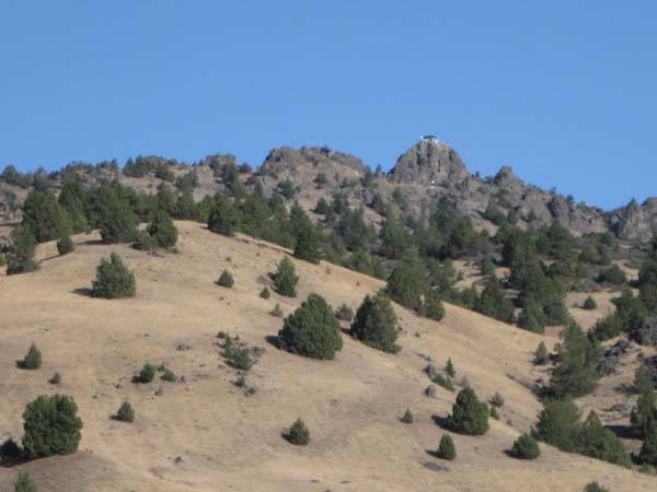
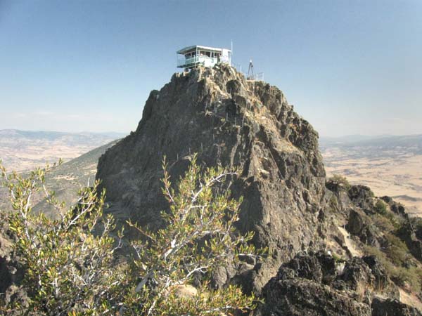
Steep, Rocky and Rugged
Craggy is an appropriate name for this site. The fire lookout sits on the highest crag. The KSOR translator was located on the large rock formation to the left. Structural steel bolted to this, the southeastern face of the rock supported the solar panels and the transmitting antenna. Steel bolted to the far side of the rock supported the receiving antenna. The rock itself isolated the receiving antenna from the translator's output signal.
The two white dots beneath the lookout are located at the very end of the access road. They are the propane and fresh water tanks that supply the lookout.
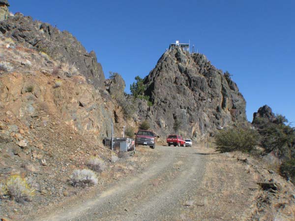
End of the Road
The last pitch of road is narrow and steep. The drop-off on the southeastern side is precipitous. At its end, the road widens to provide minimal parking and just enough space to turn around.
The battery vault for the translator sits in a small alcove at the side of the road.
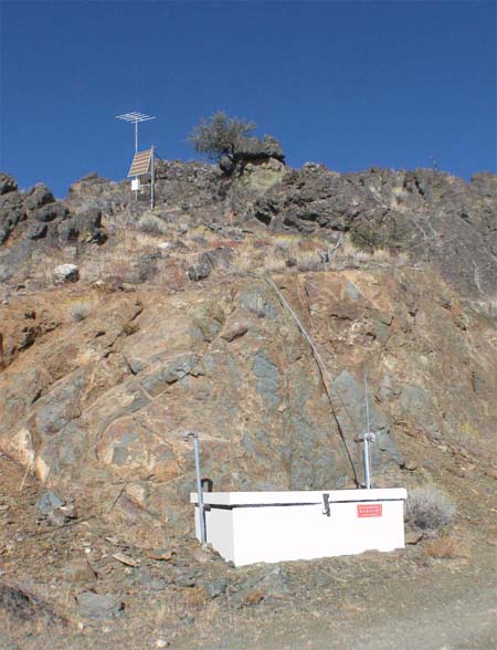
Original Installation
This photograph has been digitally altered to depict the translator site in its earliest form. The HDCA-5 transmitting antenna, solar panels and white steel box for the translator have been added. The battery vault was originally white, so its appearance was suitably altered. The ferrocement vault (seen below) was removed because it wasn't installed until a few years later.
The translator was a Tepco J-317 that delivered ten watts of power to the single transmitting antenna.
The battery box held 12 flooded lead-calcium batteries. At full charge, the bank provided 27 volts for the operation of the translator. The one-half-inch galvanized steel water pipe (running up the rock behind the vault) served as an electrical conduit for the wires connected to the translator.
To reach the translator, one had to climb the steep scree beyond the left edge of the picture. Everything was carried up by hand. Obviously, the batteries had to remain at the edge of the road: each one weighed 152 pounds and contained an electrolyte of sulfuric acid.
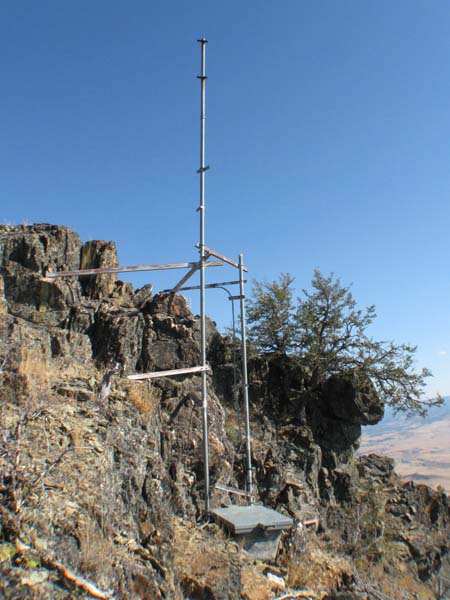
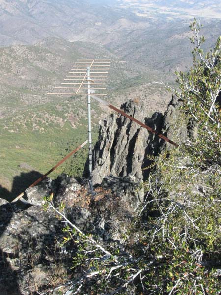
The Structure
This is the unaltered image from 2008. The translator has been decommissioned and the antennas and solar panels removed. The essential components of the structure are left.
Both of the vertical pipes supported the solar panels, while the longer pipe held the transmitting antenna on top and the steel box for the translator at shoulder height. Two of us worked together in order to plan and assemble this structure.
First, we located suitable resting places that would support the pipes with the required separation and the proper orientation for the solar panels. We marked these locations with spray paint.
Next, we measured for the horizontal braces. One person stood on top of the rock at the left while holding a fishing pole. A lead sinker was held just above one of the resting places and then the other. The fishing line provided an accurate vertical reference for the future pipe sections.
The horizontal braces were to be bolted to the rock. Later, we drilled holes in the rock with an electric roto hammer (also known as a rotary hammer or hammer drill), and used bolts with expansion shields to fasten the braces. In the initial phase, we just marked the spots for drilling with paint. Finding suitable locations was made difficult by the necessity that each steel brace fit flat against the rock surface in order to make a secure attachment. This led to a random-looking set of braces.
Following a similar procedure on the other side of the rock, we measured for the receiving antenna.
We returned to Ashland to cut and drill the angle braces. Standard 21-foot lengths of two-inch Schedule 40 steel pipe were selected for the transmitting and receiving antenna towers. A pipe section was shortened for the second solar-panel support. We returned to Craggy with pipe, braces, hardware, a roto hammer and the station's portable gasoline-electric generator. To our relief, everything fit!
Ernest Weinberg contributed immeasurably to the installation. His recollections are recorded in the Anecdotes section.
New Translator
The J-317 translator gave way to a solar optimized XL1-FM2 having dual one-watt outputs. The new translator was much larger, so the steel box was removed and a ferrocement vault set in place. This was the only ferrocement vault that was used above ground. It had the normal wood and fiberglass cover plus a fabricated steel lid for security.
The solar panels and batteries were not changed, but a second transmitting antenna was added. The mast was extended about three and a half feet to accommodate a new HDCA-10 placed under the original HDCA-5. A sleeve coupling is barely discernable in the photograph. (This short extension was digitally removed from the photograph of the original installation, above.)
Receiving Antenna
The HDCA-10 antenna was added to this picture with digital software. It received the signal directly from Mt. Baldy. Although the signal path had significant knife-edge diffraction (this phenomenon is discussed on the Coast Guard Hill page), the signal strength was ample.
Work on the receiving antenna was dangerous. A climbing belt and a safety rope were always used. Modern safety standards would require a greater degree of protection.
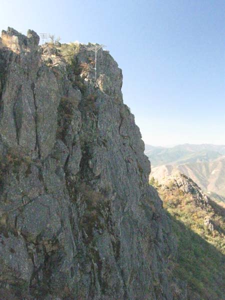
Northwest Wall
This picture is digitally altered with the addition of the HDCA-10 receiving antenna and the HDCA-5 transmitting antenna. It was taken from part way up the path to the lookout.
There was a narrow ledge at the base of the receiving antenna tower. It was just wide enough to support one's weight while installing the antenna tower, but offered no protection from the 200-foot drop off below.
The Lookout
This is the view from the top of the rock that separates the antennas. There is a narrow path to the lookout on both the northwest and southeast sides of the crag.
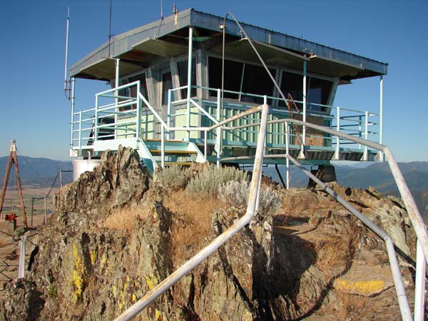
On Top
This lookout is solidly attached to the rock, and for decades, has withstood earthquakes, high winds and lightening. The drop off is breathtaking on all sides.
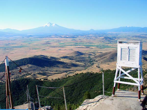
Panorama South
From left to right on the horizon, you see Mt. Shasta, Black Butte and snowcapped Mt. Eddy. Park Mountain, site of the translator for Weed, Lake Shastina and Gazelle, is barely distinguishable at the right-hand edge of the picture. Montague and Weed are hidden by small hills, and Yreka is beyond the right edge of the picture.
Topographic Map
Hawkinsville Quadrangle, U. S. Geological Survey
CONTOUR INTERVAL 10 METERS
Geographic Coordinates from the GPS: 41° 48' 52"N, 122° 32' 46"W (NAD27)
Antenna Height Above Mean Sea Level: 1,490 meters (4,888 feet)